
LINEMANN AIR BLASTERS
HOPPER DISCHARGE SYSTEM – continuous control of material flow
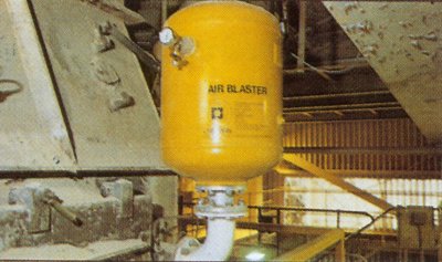
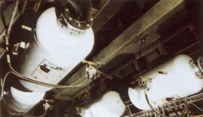
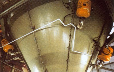
From concept through to commissioning, we will install and maintain a system of Air Blasters which discharge compressed air at high velocity into the material within the storage vessel, displacing it and restoring the normal free flow pattern.
The Air Blasters are placed in situ and fired in a particular pattern according to the location of the flow problem, the design of the vessel and the characteristics of the material stored.
Whatever the material – coal fines, cement, sand, ore, salt, chocolate, wheat, sugar, etc. – we assess each problem individually on site and propose a cost effective solution. From a single push-button system to one with multi-programmable logic control, we guarantee the equipment’s performance throughout its life.
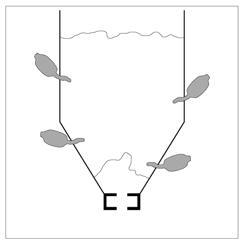
CLINGING
The build up of materials around the sides of the storage vessel reduces its useful capacity and requires more frequent filling. Old material breaking free will contaminate current production.
Linemann Air Blasters will trim the sides of the container and then prevent the build up.
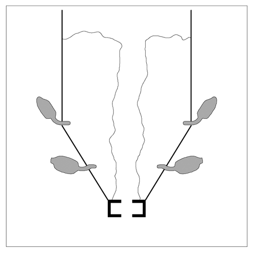
RATHOLING
This is a more serious form of clinging and reduces the capacity of the vessel to such a degree that only the central channel is available. Previously, only manual clearing, air or water hosing was available with consequent contamination of the product or damage to the vessel.
Linemann Air Blasters will cure this and prevent its recurrence.
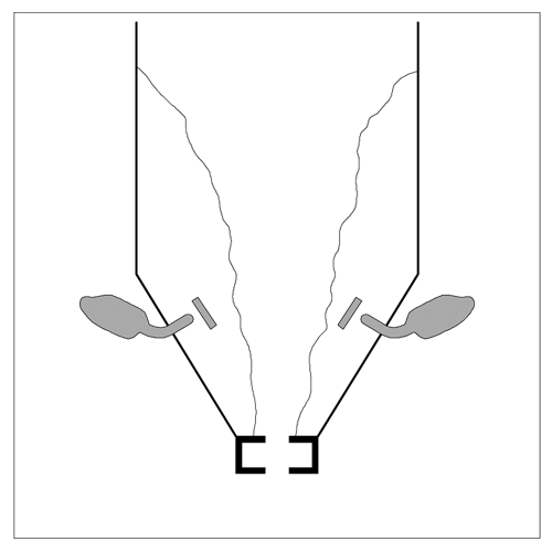
BRIDGING
This is a common problem, especially with fine materials. Bridging across the outlet results in complete loss of production and costly down time.
Hammering the area around the outlet is a time consuming exercise and eventually results in damage to the structure.
Correct sitting and firing of Linemann Air Blasters will restore flow.
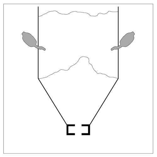
ARCHING
High arching is a very difficult problem to cure manually and case histories reveal that, with operators prodding from underneath, potentially the most dangerous one.
Blasters sited high on the vessel side will collapse the arch and restore flow quickly and efficiently with no danger to personnel.
Air Blaster Information
The inconsistent material behaviour of certain bulk solids has created an increasing demand for Air Blasters. In order to maintain production and safety standards, consideration should therefore be given to the inclusion in the design of the silos and hoppers that hold these solids, particularly where economics and technical constraints prevail.
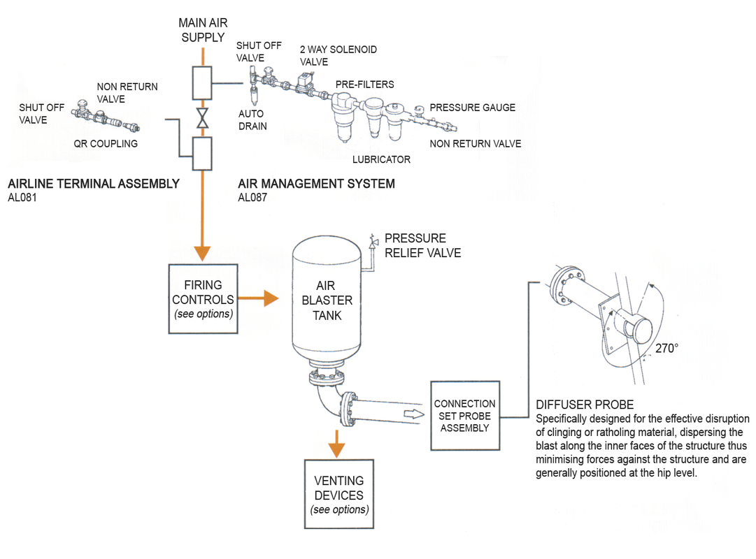
In order to ensure maximum performance and effectiveness when selecting Air Blasters, due consideration should be given to the engineering of the control system.
Whilst the Air Blaster provides the disruptive force, there are three other factors fundamental to the system’s successful operation.
- Probe selection ensures that the blast into the structure is dispersed to create maximum material movement.
- The method of operation plays a major part in determining the technical and cost levels.
- The air management system ensures operating and maintenance reliability.
FEATURES
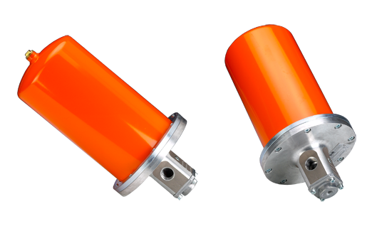
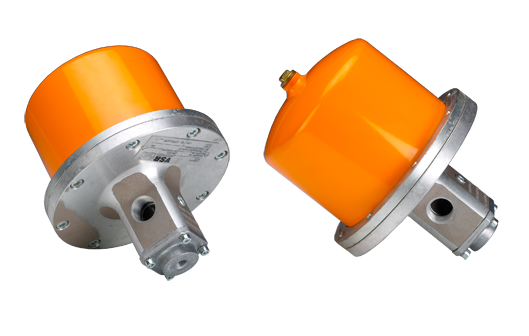
- Internal valve
- Straight line flow characteristics
- Integral to air receiver more compact design
- Rapid fill for quick firing
EXTERNAL
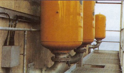
- Ideal for multi point installations using a common air receiver
The sizing and positioning of Air Blasters is not a definite science, being dependent on the behaviour of the material together with the area and height of the structure. In order to perform an anti-bridging function, Air Blasters are positioned at a low level above the outlet. When a structure’s designed capacity is dramatically reduced by the ratholing and clinging of material, it is necessary for Air Blasters to be positioned at high level to remove build up.
The following sizes are a guide based on bulk density of 1000 Kg/M, but remember quantities of Air Blasters depend on application:
Larger capacity Air Blasters are more cost effective. In all cases, it is recommended that the manufacturer be consulted to confirm the design to achieve the warranted result.
STRUCTURE CAPACITY
Up to 50 tonnes
Up to 150 tonnes
Up to 250 tonnes
Up to 300 tonnes
CAPACITY OF AIR BLASTER
18 litres
50 litres
150 litres
300 or 600 litres
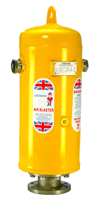
Air Blaster Specification
Developed to meet the most demanding operating requirements whatever the application, Linemann Air Blasters also satisfy the highest standards of safety and reliability.
Available in a range of sizes and cubic capacities, they enable the most efficient and cost effective systems to be designed to suit the variations in materials characteristics and hopper design.
Air receivers are constructed to account for cyclic loading to BS EN 286 Class 1, 2 or 3 and operate at minimum 6 bar air line pressure.
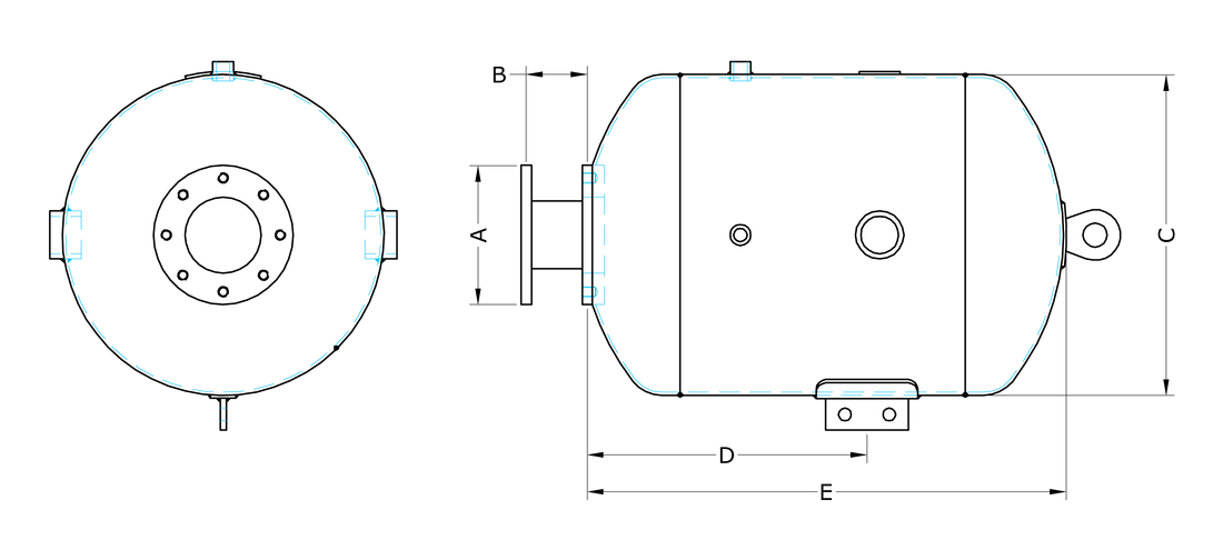
| SERIES | VALVE SIZE | A | B | C | D | E | FLANGE DETAILS | VOLUME (LITRE) |
|---|---|---|---|---|---|---|---|---|
| 1 | 63.5 | 185 | 45 | 203 | 400 | 600 | 4 x 18mm x 145 pcd | 18 |
| 2 | 100 | 215 | 106 | 305 | 475 | 700 | 8 x 18mm x 180 pcd | 50 |
| 3 | 100 | 215 | 106 | 508 | 450 | 760 | 8 x 18mm x 180 pcd | 125 |
| 4 | 150 | 285 | 138 | 610 | 895 | 1263 | 8 x 22mm x 240 pcd | 300 |
| 5 | 150 | 285 | 138 | 762 | 1145 | 1525 | 8 x 22mm x 240 pcd | 600 |
| Air Pressure Bars (PSI) | Series 1 | Series 2 | Series 3 |
|---|---|---|---|
| 5.5 (80) | 125 | 310 | 880 |
| 6.9 (100) | 155 | 375 | 1070 |
| 8.0 (120) | 185 | 440 | 1255 |
Operation & Safety
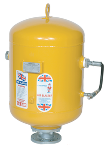
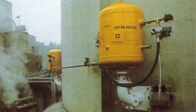
The Air Blaster is a patented device, which allows the controlled rapid release of compressed air to be directed into material stored within a bunker. the Air Blaster consists of a storage pressure vessel designed to BSEN 286 cyclic loading, an integral high performance valve and inter connecting pipe which allows the Blaster to be connected to an external air supply.
The Air Blaster is fitted to a specially designed outlet probe. The external air supply is connected to the Air Blaster by means of a pneumatic solenoid valve (optional), which also controls the operation of the Air Blaster.
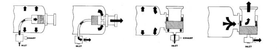
The Air Blaster works on the principle of compressed air being fed through the pneumatic valve, via the interconnecting pipe to the integral valve body – this air seats the internal piston. Air is bled from the rear to the valve body via a non-return valve into the storage vessel; when the vessel reaches line pressure, air flow ceases.
To operate the Air Blaster, a signal is fed to the pneumatic valve which then changes over closing the inlet port and opening the exhaust port; air then flows from the rear of the piston via the interconnecting pipe to atmosphere. Air stored within the vessel cannot be fed back into the integral valve, hence the non-return valve.
The air stored exerts pressure on the leading edge face of the piston and as there has been a pressure drop on the back of the piston the stored pressure pushes the piston back, exposing the massive exhaust ports. The air then flows through these ports and is directed via the outlet probes into material stored within the bunker.
The time take to operate an Air Blaster is approximately 25 milliseconds.
Air Blaster Applications
COAL
Linemann Air Blaster systems are installed extensively in the coal industry, above and below ground. Underground installations create their own problems and require special equipment and engineers – which we provide.
CEMENT
PROCESS INDUSTRIES
POWER
It is essential for power stations, which consume vast quantities of coal, to have continuous supplies. To ensure this, we have installed suitable systems of Air Blasters in many stations in the UK, as well as overseas.
QUARRYING
The push button now replaces the hammer.
Other Applications
- Asbestos producers
- Asphalt plants
- Bakery products
- Battery manufacturers
- Breweries and distilleries
- Canning and preserving fruits, vegetables and sea foods
- Chemicals and allied products
- Clay refractory manufacturers
- Coal yards (wholesale – retail)
- Coffee manufacturers
- Concrete products
- Confectionery and related products
- Cotton seed meal producers
- Crushed stone
- Flour mills
- Foundries
- Glass manufacturers
- Grain mill products
- Inks
- Insect powder manufactures
- Lead product manufactures
- Mining
- Paints and allied products
- Paper and allied products
- Petroleum refining
- Petroleum refining
- Pharmaceutical
- Plastic materials
- Powdered milk producers
- Polish manufacturers
- Porcelain
- Powder plants
- Precast concrete
- Pulp mills
- Railroads
- Steel plants
- Sugar refineries
- Timber and wood products
Erpulsors
The Erpulsor is a totally pneumatic mini blaster and bridges the specification gap between Vibrators and Air Blasters for solving flow problems. They are unique in agitating fine powders in flue ducts, bottle tops, shredded pulp and other unique applications.
They are extremely cost effective and only use air pulsing, avoiding continuous use of compressed air.
- For blowing out funnels, pipes and filters.
- For impulse aerating of bulk goods and soil.
- For blowing out of moulds and tools.
- For cleaning probes and heat exchangers.
| Operating Pressure | Max. 10 Bar |
| Test Pressure | 20 Bar |
| Vessel | Steel |
| Valve Cover | UG Ai 9 Mg |
| Operating Temp. | -20°C up to 80°C |
| Fluidization Mushroom | Polyurethane |
| Weight | 3.5Kg up to 4Kg |
| Content | 2 litres resp. 5 litres R 3/4″ outlet diameter |
The air injector stores compressed air which is released in milliseconds. The air flow and the expansion of air creates the disruptive energy for destroying particle build ups.
- To fluidise fine materials.
- For increasing flow and discharge materials.
Generally, the air injectors are fully charged. They are either fired individually or together in series. The firing is via a solenoid or manual valve, the use of solenoids enables control to be remote or cycle sequencing.
Accessories
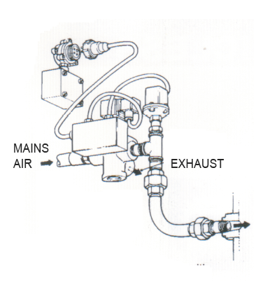
FIRING CONTROL OPTIONS
Option 1 – Air Pilot Operated Poppet Valve
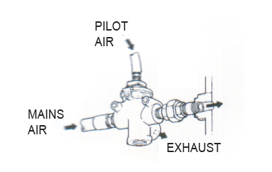
- No electrical supply required.
- Can be used in hazardous areas.
- Simple installation.
- Minimum capital costs.
Option 2 – Quick Exhaust Valve with electrical solenoid coil.
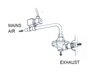
- Small bore (8mm) pipework.
- Reduced electric cabling.
- Remote operation facility.
Option 3 – Electrically Operated Valve
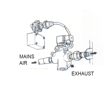
- One moving part.
- Rapid refill / operating frequency.
- Remote operation facility.
- Robust construction.
- Modular assembly.
- Easy maintenance.
Option 4 – Electrically Operated Valve With Pressure Sensor
- Rapid refill / operating frequency.
- Remote operation.
- Remote monitoring.
- Modular assembly – easy maintenance.
- Totally flexible control.
- PLC compatible.
- Integrates with plant automation.
VENTING OPTIONS
Option 1 – Auto Vent Assembly
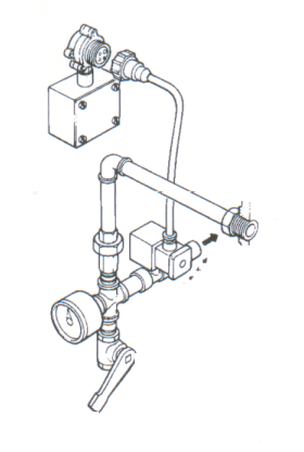
Used in conjunction with firing valve and pressure switch to give a fail safe system when electrically isolated.
Commonly used in Air Blaster systems installed on structures where human access isn’t possible.
Option 2 – Manual Vent Assembly
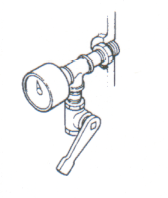
Standard equipment on all Air Blasters comprising of air vent, valve and pressure gauge.